
概要
Summary
In the previous tutorial, we rendered a cube from model space to the screen. In this tutorial, we will extend the concept of transformations and demonstrate simple animation that can be achieved with these transformations.
The outcome of this tutorial will be an object that orbits around another. It would be useful to demonstrate the transformations and how they can be combined to achieve the desired effect. Future tutorials will be building on this foundation as we introduce new concepts.
前のチュートリアルでは立方体をモデル空間から画面空間へ描画しました。今回は座標変換の概念を拡張して単純なアニメーションを実践します。これは一連の座標変換を用いて実現する事が出来ます。
このチュートリアルの成果物は他のオブジェクトの周りを公転する物体となります。
これは座標変換と、それらの結合によって望む効果を実現するための良いデモンストレーションになるでしょう。
後のチュートリアルの新しい概念は今回の内容を基礎に置く事になるでしょう。
座標変換
Transformation
In 3D graphics, transformation is often used to operate on vertices and vectors.
3Dグラフィクスでは, 座標変換はしばしば頂点とベクトルを操作するために使われます。
It is also used to convert them in one space to another. Transformation is performed by way of multiplication with a matrix.
また、頂点やベクトルを、ある空間から別の空間へ変換するためにも使われる。座標変換は行列の乗算によって実行されます。
There are typically three types of primitive transformation that can be performed on vertices: translation (where it lies in space relative to the origin), rotation (its direction in relation to the x, y, z frame), and scaling (its distance from origin).
典型的には、頂点に対して実行できる基本的な座標変換は3タイプあります。:平行移動(頂点が原点から見て空間中の何処に位置するか)、回転(x,y,z軸に関係した頂点の方向)、スケーリング(頂点の原点からの距離)です。
In addition to those, projection transformation is used to go from view space to projection space.
これらに加え、プロジェクション変換はビュー空間からプロジェクション空間への移動に使われます。
The XNA Math library contains APIs that can conveniently construct a matrix for many purposes such as translation, rotation, scaling, world-to-view transformation, view-to-projection transformation, and so on.
XNAの算術ライブラリは様々な目的用(平行移動や、回転、スケーリング、ワールドからビュー変換、ビューから射影変換、等々)の行列を簡単に作れるAPIを含んでいます。
An application can then use these matrices to transform vertices in its scene.
なのでアプリケーションはシーン中の頂点を座標変換するのにこれらの行列を使えます。
A basic understanding of matrix transformations is required. We will briefly look at some examples below.
行列による座標変換の基礎的な理解は必要になります。以下で簡潔にいくつかの例を見ましょう。
平行移動
Translation
Translation refers to moving or displacing for a certain distance in space.
平行移動とは、空間での一定の距離の移動や配置の事を指します。
In 3D, the matrix used for translation has the form
3D では、平行移動に使用される行列は次の様な形式となります。
1 0 0 0
0 1 0 0
0 0 1 0
a b c 1
where (a, b, c) is the vector that defines the direction and distance to move.
(a、b、c)が表す部分はベクトルです。このベクトルが移動する方向と距離を定義します。
For example, to move a vertex -5 unit along the X axis (negative X direction), we can multiply it with this matrix:
例えばX軸の負の方向に沿って-5単位 頂点を動かすには以下の行列を掛ければ良いです。
1 0 0 0
0 1 0 0
0 0 1 0
-5 0 0 1
If we apply this to a cube object centered at origin, the result is that the box is moved 5 units towards the negative X axis, as figure 5 (訳注:( ゚д゚)図5?・・・5 unitsに引きずられた?) shows, after translation is applied.
原点を中心とする立方体の物体にこれを適用する場合は、結果として、平行移動の適用後に、図 1 の様に負の X 軸方向に 5 単位移動されます。
 |
| 図1・平行移動の効果 |
In 3D, a space is typically defined by an origin and three unique axes from the origin: X, Y and Z.
3D では、空間は通常、原点と原点からの 3 つの固有の軸によって定義されます。:X,Y,Zです。
There are several spaces commonly used in computer graphics: object space, world space, view space, projection space, and screen space.
一般的に CGで使われる空間は複数あります。:オブジェクト空間、ワールド空間、ビュー空間、プロジェクション空間、スクリーン空間です。
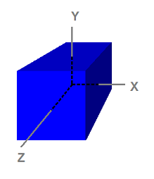 |
| オブジェクト空間に定義された立方体 |
回転
Rotation
Rotation refers to rotating vertices about an axis going through the origin.
回転とは、原点を通る軸に対して頂点を回転させることを指します。
Three such axes are the X, Y, and Z axes in the space.
それらの軸は3本あります。空間内のx、y、z軸です。
An example in 2D would be rotating the vector [1 0] 90 degrees counter-clockwise.
2D の例では、ベクトル [1 0] を反時計回りに 90°回転させています。
The result from the rotation is the vector [0 1].
この回転の結果は、ベクトル [0 1] となります。
The matrix used for rotating i degrees clockwise about the Y axis looks like this:
Y軸に対する時計回りの回転に使用される行列は、次の様になります。
cosθ 0 -sinθ 0
0 1 0 0sinθ 0 cosθ 0
0 0 0 1
Figure 6(訳注:( ゚д゚){前回figure 5って書いちゃったからそれに1足しちゃった?) shows the effect of rotating a cube centered at origin for 45 degrees about the Y axis.
図 3 は、原点を中心とする立方体を Y 軸に対して 45°回転した場合の効果を示しています。
 |
| 図3. Y 軸に対する回転の効果 |
スケーリング
Scaling
Scaling refers to enlarging or shrinking the size of vector components along axis directions.
スケーリングとは、軸方向に沿ってベクトル成分のサイズを拡大または縮小することを指します。
For example, a vector can be scaled up along all directions or scaled down along the X axis only.
たとえば、ベクトルをすべての方向に拡大することや、X 軸方向のみに縮小することができます。
To scale, we usually apply the scaling matrix below:
スケーリングには、通常は次のようなスケーリング行列を適用します。
p 0 0 0
0 q 0 0
0 0 r 0
0 0 0 1
where p, q, and r are the scaling factor along the X, Y, and Z direction, respectively.
この場合の p q r はそれぞれ x y z 方向の拡大要素です。
The figure below shows the effect of scaling by 2 along the X axis and scaling by 0.5 along the Y axis.
図 4 は、X 方向に 2、Y 方向に 0.5 でスケーリングした場合の効果を示しています。
 |
| 図4. スケーリングの効果 |
座標変換の合成
Multiple Transformations
To apply multiple transformations to a vector, we can simply multiply the vector by the first transformation matrix, then multiply the resulting vector by the second transformation matrix, and so on.
複数の座標変換をベクトルに適用するには、単純に、そのベクトルを 1 つ目の変換行列に乗算し、次に、その結果としてもたらされたベクトルを 2つ目の変換行列に乗算し、これ以降も同様のことを行います。
Because vector and matrix multiplication is associative, we can also multiply all of the matrices first, then multiply the vector by the product matrix and obtain an identical result.
ベクトルと行列の乗算は結合可能なため、最初にすべての行列を乗算してからその積にベクトルを乗算しても、同じ結果を取得できます。
The figure below shows how the cube would end up if we combine a rotation and a translation transformation together.
図 5 は、回転と平行移動の座標変換を組み合わせた場合に立方体にもたらされる結果を示しています。
 |
| 図5. 回転と平行移動の効果 |
軌道の作成
Creating the Orbit
In this tutorial, we will be transforming two cubes.
このチュートリアルでは2つの立方体を座標変換します。
The first one will rotate in place, while the second one will rotate around the first, while spinning on its own axis.
一つ目の立方体はその場で回転し、もう一つの立方体は一つ目の立方体を周りながら自分自身の軸でも回転します。
The two cubes will have its own world transformation matrix associated with it, and this matrix will be reapplied to it in every frame rendered.
2つの立方体は独自のワールド変換行列を持ち、その行列はすべての描画フレーム毎に適用されます。
There are functions within XNA Math that will assist in the creation of the rotation, translation, and scaling matrices.
XNA Mathには回転、移動、スケーリング行列を作るのを助ける関数があります。
- Rotations performed around the X, Y. and Z axis are accomplished with the functions XMMatrixRotationX, XMMatrixRotationY, and XMMatrixRotationZ, respectively.They create basic rotation matrices that rotate around one of the primary axis. Complex rotations around other axis can be done by multiplying together several of them.
- x,y,z軸周りの回転はそれぞれXMMatrixRotatinoX, ZMMatrixRotationY, XMMatrixRotationZという関数によって実行されます。これらは主軸(x,y,z)の一つを回転するという基本的な回転行列を作ります。複数の軸で回転させる複合的な回転はこれらの行列を掛け合わせる事で出来ます。
- Translations can be performed by invoking the XMMatrixTranslation function. This function will create a matrix that will translate points specified by the parameters.
- 平行移動はXMMatrixTranslation関数を呼び出す事によって実行できます。この関数は引数を指定して点を平行移動させる行列を作ります。
- Scaling is done with XMMatrixScaling. It scales only along the primary axes. If scaling along arbitrary axis is desired, then the scaling matrix can be multiplied with an appropriate rotation matrix to achieve the effect.
- スケーリングはXMMatrixScalingによって行われます。スケーリングは主軸のみに沿って行われます。恣意的な軸のスケーリングを行いたい場合、拡大行列を適切な回転行列と掛ければその効果が得られるでしょう。
The first cube will be spinning in place and act as the center for the orbit.
1 つ目の立方体は同じ位置で回転し、もう一つの公転軌道の中心の役割を果たします。
The cube has a rotation along the Y axis applied to the associated world matrix.
この立方体は関連するワールド行列によって加えられたY軸に沿った回転を持ちます。
This is done by calling the XMMatrixRotationY function shown in the following code.
これは下記のコードで示すようにXMMatrixRotationYを呼びだす事で行われます。
The cube is rotated by a set amount each frame.
立方体の回転量は各フレームの総計として現れます。
Since the cubes are suppose to continuously rotate, the value which the rotation matrix is based on gets incremented with every frame.
立方体は回転し続けることが前提となっているため、回転行列が基準とする値は、フレームごとに増大します。
// 立方体1: 原点を回る
g_World1 = XMMatrixRotationY( t );
The second cube will be orbiting around the first one.
2つ目の立方体は一つ目の周りを公転する事となります。
To demonstrate multiple transformations, a scaling factor, and its own axis spin will be added.
座標変換の合成を示すために、スケーリングの要素と、およびそれ自体の軸回転を追加しましょう。
The formula used is shown right below the code (in comments).
使われる式はコードのすぐ下にコメントで示しました。
First the cube will be scale down to 30% size, and then it will be rotated along its spin axis (the Z axis in this case).
まず立方体の大きさを30%の大きさにスケールダウンし、そしてその自転軸(この場合Z軸)に沿って回転するようにします。
To simulate the orbit, it will get translated away from the origin, and then rotated along the Y axis.
軌道をシミュレートするために、原点から離れるように平行移動させてから、そこでY軸に沿って公転させます。
The desired effect can be achieved by using four separate matrices with its individual transformation (mScale, mSpin, mTranslate, mOrbit), then multiplied together.
目的の効果は、個々の座標変換において4 つの別個の行列 (mScale、mSpin、mTranslate、mOrbit) を使用して、後で一緒に乗算することで実現できます。
// 立方体2: Rotate around origin
XMMATRIX mSpin = XMMatrixRotationZ( -t );
XMMATRIX mOrbit = XMMatrixRotationY( -t * 2.0f );
XMMATRIX mTranslate = XMMatrixTranslation( -4.0f, 0.0f, 0.0f );
XMMATRIX mScale = XMMatrixScaling( 0.3f, 0.3f, 0.3f );
g_World2 = mScale * mSpin * mTranslate * mOrbit;
An important point to note is that these operations are not commutative.
注意すべき重要な事は、これらの操作は可換ではないという事です。
The order in which the transformations are applied matter.
座標変換の順番は重要な要素の一つです。
Experiment with the order of transformation and observe the results.
座標変換の順番を実験し、結果を観察してみてちょ。
Since all the transformation functions will create a new matrix from the parameters, the amount at which they rotate has to be incremented.
全ての座標変換 関数は引数から新しい行列を作成するため、引数の回転量を指す部分を増加させる必要があります。
This is done by updating the "time" variable.
これは” time ”という変数を更新することで行われます。
(訳注:実際のコードではtimeではなく、tという名前の変数が使われています。)
// 時間の更新
t += XM_PI * 0.0125f;
Before the rendering calls are made, the constant buffer must be updated for the shaders.
レンダリングの呼び出しがなされる前に、シェーダのために定数バッファを更新する必要があります。
Note that the world matrix is unique to each cube, and thus, changes for every object that gets passed into it.
ワールド行列はそれぞれの立方体で独自のものを使う事に注意して下さい。従って、オブジェクト毎に行列を付け替えます。
(訳注:エフェクトファイル(Tutorial05.fx)内のシェーダー定数は相変わらず1セット(ConstantBuffer内のWorld,View,Projection)だけを使い、C++プログラムコード側からそれを更新することで2つの立方体を書き分けています。)
//
// 最初の立方体の更新
//
ConstantBuffer cb1;
cb1.mWorld = XMMatrixTranspose( g_World1 );
cb1.mView = XMMatrixTranspose( g_View );
cb1.mProjection = XMMatrixTranspose( g_Projection );
g_pImmediateContext->UpdateSubresource( g_pConstantBuffer, 0, NULL, &cb1, 0, 0 );
//
// 最初の立方体の描画
//
g_pImmediateContext->VSSetShader( g_pVertexShader, NULL, 0 );
g_pImmediateContext->VSSetConstantBuffers( 0, 1, &g_pConstantBuffer );
g_pImmediateContext->PSSetShader( g_pPixelShader, NULL, 0 );
g_pImmediateContext->DrawIndexed( 36, 0, 0 );
//
// 2つ目の立方体の更新
//
ConstantBuffer cb2;
cb2.mWorld = XMMatrixTranspose( g_World2 );
cb2.mView = XMMatrixTranspose( g_View );
cb2.mProjection = XMMatrixTranspose( g_Projection );
g_pImmediateContext->UpdateSubresource( g_pConstantBuffer, 0, NULL, &cb2, 0, 0 );
//
// 2つ目の立方体の描画
//
g_pImmediateContext->DrawIndexed( 36, 0, 0 );
深度バッファ
The Depth Buffer
There is one other important addition to this tutorial, and that is the depth buffer.
このチュートリアルにはもう一つ重要な追加があります。それは深度バッファです。
Without it, the smaller orbiting cube would still be drawn on top of the larger center cube when it went around the back of the latter.
これがないと小さい公転立方体が、中央の大きい立方体の後ろに回った後も、まだ描画されてしまいます。
The depth buffer allows Direct3D to keep track of the depth of every pixel drawn to the screen.
深度バッファーは、Direct3Dが画面に描画された全てのピクセルの深さを追跡する事を可能にします。
The default behavior of the depth buffer in Direct3D 11 is to check every pixel being drawn to the screen against the value stored in the depth buffer for that screen-space pixel.
Direct3D 11の深度バッファーのデフォルトの動作では、画面に描画されている全てのピクセルが、そのスクリーン空間のピクセル用の深度バッファーに格納された値に対してチェックされます。
If the depth of the pixel being rendered is less than or equal to the value already in the depth buffer, the pixel is drawn and the value in the depth buffer is updated to the depth of the newly drawn pixel.
もし描画されたピクセルの深さが既に深度バッファの中にある値以下の場合、そのピクセルは描画されます。そして新たに描画されたピクセルが新しい深度バッファの値になります。
On the other hand, if the pixel being draw has a depth greater than the value already in the depth buffer, the pixel is discarded and the depth value in the depth buffer remains unchanged.
一方、描画しようとするピクセルが既に深度バッファの値より大きければ、そのピクセルは破棄され、深度バッファも変更されません。
The following code in the sample creates a depth buffer (a DepthStencil texture).
サンプル中の以下のコードは深度バッファ (深度ステンシルテクスチャ)を作ります。
It also creates a DepthStencilView of the depth buffer so that Direct3D 11 knows to use it as a Depth Stencil texture.
サンプル中では深度バッファの深度ステンシルビュ-も作ります。これにより、Direct3D11はそれを深度ステンシルテクスチャとして使うことを知ります。
// 深度ステンシル・テクスチャの作成
D3D11_TEXTURE2D_DESC descDepth;
ZeroMemory( &descDepth, sizeof(descDepth) );
descDepth.Width = width;
descDepth.Height = height;
descDepth.MipLevels = 1;
descDepth.ArraySize = 1;
descDepth.Format = DXGI_FORMAT_D24_UNORM_S8_UINT;
descDepth.SampleDesc.Count = 1;
descDepth.SampleDesc.Quality = 0;
descDepth.Usage = D3D11_USAGE_DEFAULT;
descDepth.BindFlags = D3D11_BIND_DEPTH_STENCIL;
descDepth.CPUAccessFlags = 0;
descDepth.MiscFlags = 0;
hr = g_pd3dDevice->CreateTexture2D( &descDepth, NULL, &g_pDepthStencil );
if( FAILED(hr) )
return hr;
// 深度ステンシル・ビューの作成
D3D11_DEPTH_STENCIL_VIEW_DESC descDSV;
ZeroMemory( &descDSV, sizeof(descDSV) );
descDSV.Format = descDepth.Format;
descDSV.ViewDimension = D3D11_DSV_DIMENSION_TEXTURE2D;
descDSV.Texture2D.MipSlice = 0;
hr = g_pd3dDevice->CreateDepthStencilView( g_pDepthStencil, &descDSV, &g_pDepthStencilView );
if( FAILED(hr) )
return hr;
In order to use this newly created depth stencil buffer, the tutorial must bind it to the device.
これを新しく作られた深度ステンシルバッファとして使うためには、デバイス(コンテキスト)に結び付ける必要があります。
This is done by passing the depth stencil view to the third parameter of the OMSetRenderTargets function.
これは深度ステンシルビューをOMSetRenderTargets関数の3つ目の値へ渡す事で出来ます。
g_pImmediateContext->OMSetRenderTargets( 1, &g_pRenderTargetView, g_pDepthStencilView );
As with the render target, we must also clear the depth buffer before rendering.
レンダーターゲットと一緒で、深度バッファも 描画前に クリアする必要があります。
This ensures that depth values from previous frames do not incorrectly discard pixels in the current frame.
これにより、前のフレームの深度値によって今のフレームのピクセルが誤って破棄される事が防がれます。
In the code below the tutorial is actually setting the depth buffer to be the maximum amount (1.0).
以下のチュートリアルのコードでは実際に深度値を最大値(1.0)にセッティングしています。
//
// Clear the depth buffer to 1.0 (max depth)
//
g_pImmediateContext->ClearDepthStencilView( g_pDepthStencilView, D3D11_CLEAR_DEPTH, 1.0f, 0 );
(訳注:なぜか原著ではこのサンプルコードが抜けていました。)

0 件のコメント:
コメントを投稿